
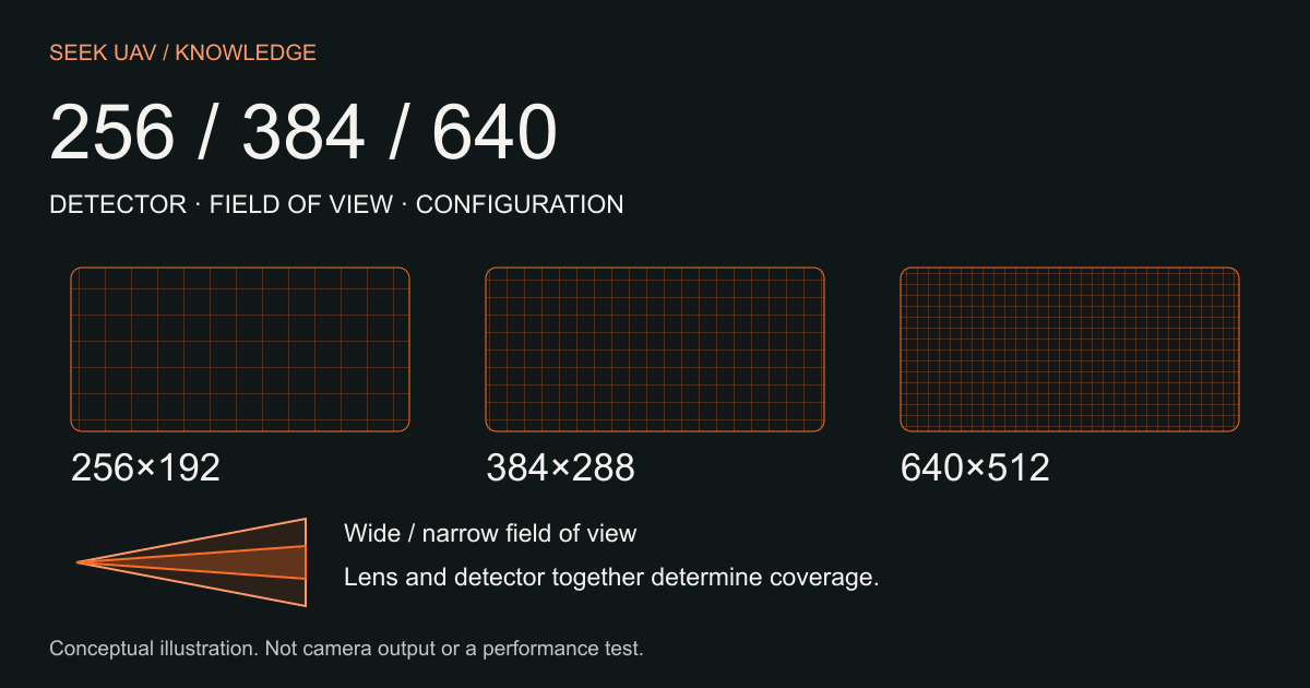
Choosing a thermal camera for a drone starts with the image your project needs, the scene you need to cover, and the receiving system. A larger detector gives you more samples across a scene when the field of view is held constant. It does not, by itself, establish useful range, image quality, or compatibility. Compare resolution together with the lens, frame rate, output, and complete installed package.
This guide explains how to compare a 256×192, 384×288, or 640×512 UAV thermal imaging module. It is a documented selection guide, rather than a hands-on performance test. The SEEK specifications below come from the supplied SEEK UAV datasheet; confirm the delivered configuration and document revision when requesting a quotation. [1]
What do 256, 384, and 640 actually mean?
The short model descriptions usually refer to the horizontal size of the native thermal detector. The full dimensions matter: 256×192 contains 49,152 detector pixels, 384×288 contains 110,592, and 640×512 contains 327,680. These counts are simple multiplication of the stated detector dimensions, not measurements of scene detail.
The three arrays also have different proportions. The first two are 4:3, while 640×512 is 5:4. A recording or display may crop, stretch, or add borders to fit another shape. Ask whether a sample image shows the whole detector, a crop, or an enlarged video frame before judging the apparent difference.
For an FPV thermal module or another compact camera, the useful question is what information survives from detector to display. A high-resolution sensor can be paired with an output or screen that cannot show all its detail. Conversely, a large video frame does not prove that the detector captured that many independent thermal samples.
Compare the documented resolution classes
| Parameter | SEEK 256 | SEEK 384 | SEEK 640 |
|---|---|---|---|
| Native thermal array [1] | 256×192 | 384×288 | 640×512 |
| Detector pixels, calculated | 49,152 | 110,592 | 327,680 |
| Documented frame-rate options [1] | 25 / 50 Hz | 30 / 60 Hz | 30 / 60 Hz |
| What still needs configuration-specific confirmation | Lens, field of view, output mode, complete weight | Lens, field of view, output mode, complete weight | Lens, field of view, output mode, complete weight |
The frame-rate entries describe options in the supplied family datasheet. They do not mean that every output, firmware revision, and recording mode provides every listed rate. Obtain the selected mode in writing. The table compares documented detector classes, not matched lenses or independently tested cameras.
Keep native resolution separate from enhanced output
Native resolution describes the detector array. Output resolution describes a video stream, recorded frame, or file. Display resolution describes the screen. These are three separate specifications and should appear separately in a comparison.
Resizing can make a low-resolution frame easier to view on a larger screen. Sharpening and other processing can change its appearance. Neither an enlarged file nor a sharper outline establishes that the native detector has changed. If a supplier describes super-resolution or another enhancement, ask how it is produced and whether the comparison uses equivalent processing.
For a useful evaluation, request an original recording and its stated acquisition mode. A compressed social-media clip or a screenshot of a display may hide the difference you are trying to assess. Keep the original file alongside the model, lens, firmware, and recording settings so you can revisit the comparison later.
Lens choice and field of view change the result
Field of view is the angular extent of the scene visible through the camera. Lens choice and detector geometry affect how that scene is sampled. The same focal length on different detector formats is not a guarantee of equal coverage. FLIR's lens guidance explains why field of view and spatial resolution need to be considered together. [2]
Consider two inspection photographs of the same building facade. If one camera shows the whole facade and another shows only a window, the second image can make that window look more detailed even before the detector resolution is considered. The comparison has changed both coverage and sampling. It is not evidence that one resolution class universally performs better.
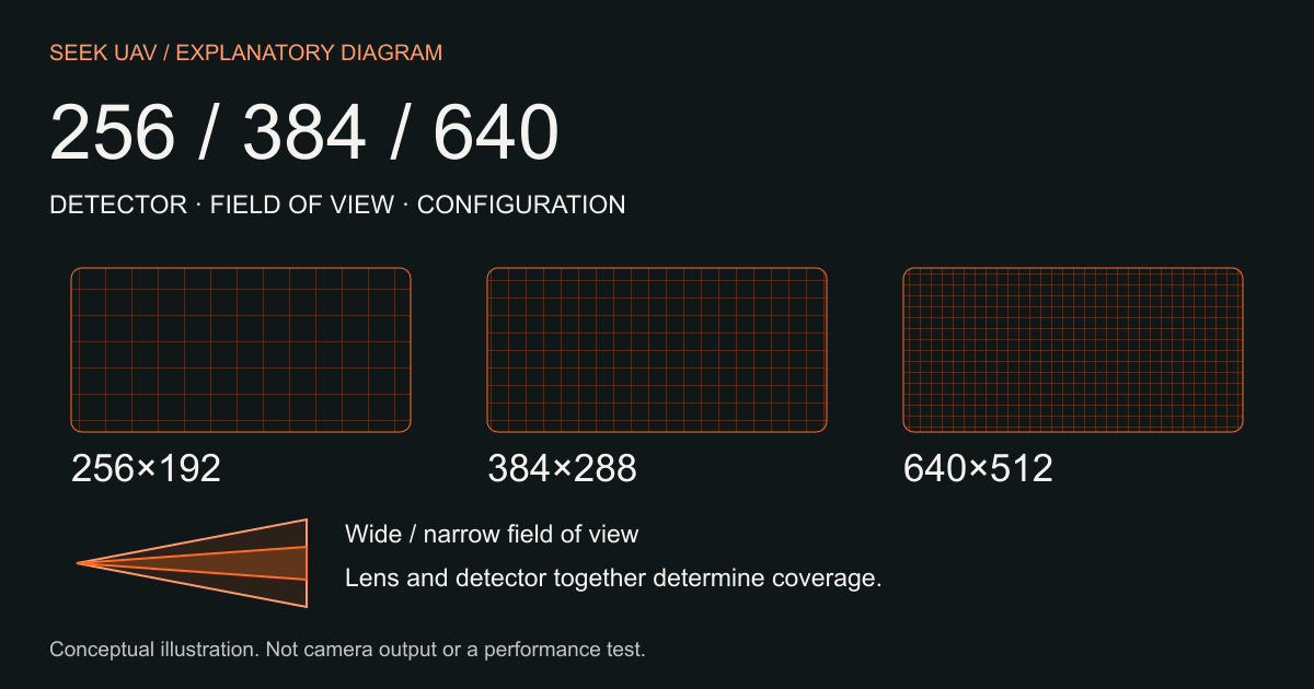
Ask for horizontal and vertical field of view for the actual lens/module combination. If you compare images, record whether you held the camera position, scene coverage, or lens choice constant. Explain that choice in the caption. A fair comparison makes the changed variables visible rather than allowing the reader to infer them.
Check the constraints that pixel count cannot answer
Thermal sensitivity and temperature accuracy are different ideas. Sensitivity concerns small thermal differences; accuracy concerns how well a measurement agrees with temperature. A thermal image is not, on its own, proof that calibrated temperature data is available. Verify radiometric capability and the accessible data format separately if your inspection needs numeric temperatures. [3]
Frame rate describes image updates, while end-to-end delay includes the camera and the receiving chain. Do not substitute a detector time constant or the interval between frames for a measured glass-to-glass latency figure. For buying purposes, ask how a quoted delay was measured and which hardware and processing stages it includes.
Weight also needs a defined boundary. The supplied datasheet labels its mass figures as without the lens. A complete installed camera can additionally include the lens, housing, interface board, cables, and mounting parts. Compare the same boundary across offers, and ask which accessories are included in the quoted price.
Power requirements should cover the chosen operating mode and the delivered assembly. Output selection also matters: a USB-labelled module, a CVBS camera, and a MIPI configuration may require different receiving hardware and documentation. Our companion interface guide provides a separate checklist for that decision.
A practical selection process
 Describe the ordinary scene and the detail you need to assess. Specify whether the task is viewing thermal patterns or obtaining calibrated measurements.
- Set the required scene coverage, then request lens and field-of-view information for each candidate configuration.
- Compare native detector dimensions, output mode, and display or recording requirements separately.
- Request complete mass, power requirements, included accessories, and current interface documentation.
- Evaluate a sample against a written acceptance checklist before committing to a larger order.
Use this process to create a shortlist, rather than choosing a universal winner. A 256 module deserves evaluation when it meets the actual viewing requirement. A 384 or 640 configuration deserves evaluation when additional sampling is relevant at the required coverage. The acceptance test, not the model number alone, determines whether the selected module meets your project.
Make a sample comparison reproducible
A useful sample record includes the model identifier, hardware revision, lens, field of view, firmware, output mode, capture method, scene, and conditions. Keep the camera position and the processing assumptions explicit. An ordinary facade, equipment enclosure, or other static non-sensitive scene is enough to test whether the image supports your intended assessment.
Record what counts as a pass before inspecting the sample. Examples include a usable view of the required scene, a documented supported video format, and a readable recording on your receiving system. Avoid turning a single attractive image into a general range or weather-performance claim. Retain unsuccessful samples too: they help distinguish a configuration problem from a requirement that needs to change.
Explore SEEK modules
The catalogue is the starting point for model enquiries. For a useful response, send your desired resolution class, scene coverage, receiving system, and whether calibrated temperature data is required. Ask for the current specification of the proposed assembly rather than assuming that a family datasheet defines every available combination.
References
Questions & answers
Is a 640 thermal camera always the best choice?
No universal choice follows from the pixel count. Evaluate the required coverage, lens, output, complete mass, power, and the detail visible in a representative sample. More detector pixels can help at matched coverage, but the full configuration still has to meet your requirements.
Does 640×512 video prove that the detector is 640×512?
No. A file or stream can be resized or cropped. Ask for native detector dimensions and the processing and output mode separately. Compare original recordings with clear labels.
Can I compare modules using the same focal length?
You can record that comparison, but it may not hold field of view constant. Ask for actual coverage for each detector/lens combination and explain which variables differ before drawing a conclusion.
Does a thermal module measure temperature?
Not necessarily. Confirm radiometric capability, calibration conditions, accuracy specifications, and access to temperature data for the exact configuration. A visible thermal image alone does not establish those capabilities.
What should I send with a SEEK module enquiry?
Send the required scene coverage, preferred resolution class, receiving hardware, desired output, complete weight and power constraints, quantity, and documentation needs. Include whether you need thermal viewing or calibrated measurements.